Last Updated on October 11, 2025 by Muhamed Elmesery
Imagine your daily life without lamps, working fans, and domestic appliances like electric stoves, A/C, and more. Also, modern means of transportation and communication.
If there is no electricity in our world, what about factories? large machines? essential items like food, cloth, paper, and many other things that are produced based on electricity?
Actually, electricity is one of the most important blessings that science has given to mankind. It has also become a part of modern life and one cannot think of a world without it.
Create a FREE Virtual Labs Account Now!
The discovery of electricity changed lives drastically, starting from domestic use to industrial activities. It is one of the most important innovations of all time.
In your house, electricity is important for operating all appliances, entertainment, lighting and of course, all technology.
When it comes to travelling, electricity is important for the use of electric trains, airplanes and even some cars.

If you think about facilities such as schools, medical facilities such as hospitals, and retail facilities, all need electricity to run efficiently.
When it comes to the medical field, electricity allows for the availability of X-Rays, ECG’s and instant results regarding blood tests, as well as anything else. It allows for a more efficient medical practice in these facilities.
Electricity is also important for the purpose and operation of machines such as computers or monitors that display data to enhance medicine. Without electricity, hospitals and medicine would not be able to be advanced and cure illnesses, which would also result in more casualties.
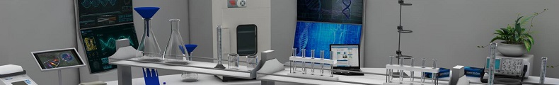
Through this article, we will try to cover the history of electricity, the main physical concepts about it, and the virtual electricity experiments that are provided by the PraxiLabs virtual lab.
Table of Contents
History of Electricity
Beginning of Electricity
The first observation of electricity phenomenon in history dates all the way back to 500 B.C. when Thales of Miletus discovered static electricity by rubbing fur on amber.
Two thousand years later, in the 1600s, the English physician and physicist William Gilbert published the first theories about electricity in his book, De Magnete.
The next major text about electricity experiments and notes about the Mechanical Origin or Production of Electricity was published in 1675 by English chemist and physicist Robert William Boyle.
In the early 1700s – decades before Franklin’s kite – English scientist Francis Hauksbee made a glass ball that glowed when rubbed while experimenting with electrical attraction and repulsion. The glow was bright enough to read by, and this discovery would eventually lead to neon lighting a few centuries later.
Fast forward to September 1882, when a house in Appleton, Wisconsin became the first American home to be powered by hydroelectricity. The station that powered the home used the direct current (DC) system developed by Thomas Edison. Over the next several years, “the direct current versus alternating current (AC)” debate captured attention, as Thomas Edison and George Westinghouse (who championed AC), competed for contracts.
Until the early nineteenth century, AC was not known yet. It was only when Michael Faraday’s experiments started to shine, that AC began to be a familiar term. Alternating current contributed greatly in the journey of reconstructing and forming our knowledge and perception of electromagnetism. Thanks to that, we were able to get the best benefits out of electromagnetism by indulging it into both the commercial life and the practical one.
Try PraxiLabs Virtual Lab For FREE!
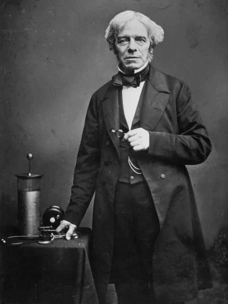
After Michael Faraday’s experiments, the curiosity of knowledge moved to the United States of America, where a special scientific conflict we call today (Currents War) began.
In 1882, Thomas Edison founded the world’s first electrical power station in New York City to illuminate the Manhattan area using DC. However, after William Stanley invented the electrical transformer in 1885, the world began to move to a new stage that would irritate Mr. Edison and hurt his investments in DC, and this is what really happened with the discovery of AC by Nicola Tesla when inventing the engine that relies on AC current.
Then the United States divided into two teams, the first team calling for the use of AC power developed by Tesla and the Westin House, which started building its stations and ensured lower cost in the transmission and distribution operations, and the second team led by the inventor Edison, who illuminated New York for the first time and who promotes his direct current. He tried to prove that AC is dangerous, by shocking the animals with alternating current.
Read our blog about The Current War.
At the end of this battle, AC prevailed, because of the limited distance from which DC can be transferred, unlike AC which is easy to transport to remote places.
AC and DC Currents
AC
AC is an electric current that periodically reverses direction, in contrast to direct current (DC) which flows only in one direction. Alternating current is the form in which electric power is delivered to businesses and residences, and it is the form of electrical energy that consumers typically use when they plug kitchen appliances, televisions, fans, and electric lamps into a wall socket.
3 Advantages of Alternating Current (AC)
1- The electrical power resulted from alternating current (AC) surpasses that of the direct current (DC), both practically and economically. This AC power can be transmitted too far between countries, or even across different continents! This feature is by all means not applicable by the usage of DC.
2- AC is capable of transmitting information. For example, a loudspeaker converts a word’s contained information into AC.
3- Being eco-friendly. Where alternating current can be easily generated from water or wind turbines.
Direct Current (DC)
A famous example of DC power is the battery. Direct current, simply abbreviated as DC, is a unidirectional flow of electric charges. DC can flow through conductors, such as wires, as well as semiconductors, and insulators. It can also flow through vacuum, just as the electron beams or the ion ones.
With its constant directed electric current flow, the DC is thus distinguished from its counterpart, the alternating current (AC). The term galvanic current was formerly used to describe this type of current.
Applications of the Direct Current
For underwater cables and transmitting electrical energy over very long distances, high voltage DC is our preferable choice. Low voltage applications also use DC, such as batteries which generate constant current. Since they cannot generate AC, solar cells also rely on DC, and are being used in photovoltaics.
6 Direct Current (DC) Advantages
- The polarity does not reverse when direct current is used. Hence, the electrodes should be well accounted for whenever connecting an electrical circuit to DC.
- By using a “wave bridge rectifier”, AC is easily converted into DC.
- The magnetic stability that comes with DC is the reason behind the flow of its electrons.
- It gives a constant value with time, undergoing no variations.
- Its power factor is always equal to one.
- The detected wave of DC looks like a wave of continuous pulses.
The Evolution of Wiring and Electrical Components
In the earliest days of home electrification, electricity was often carried place to place by bare copper wires with minimal cotton insulation. Sockets, switch handles, and fuse blocks were made of wood.
There were no voltage regulators and lights would dim and brighten in response to demand placed on the electrical grid.
From about 1890 to 1910, knob and tube wiring was used for electric installation. In this early set-up, hot wires and neutral wires were run separately and were insulated using rubberized cloth, which degraded over time.
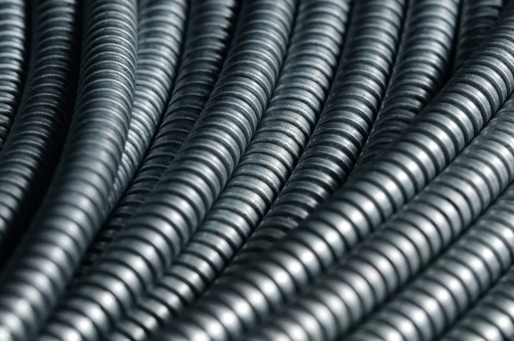
From the 1920s to the 1940s, flexible armored cable, which offered some protection from wire damage, became commonplace. During the 1940s, electricians began using metal conduit, in which several insulated wires were enclosed in rigid metal tubes.
During these years, the potential for danger was much higher than it is today because wires weren’t grounded. If one of the “hot” wires became damaged or some other mishap caused the electrical current to escape the wiring pathways, fire or severe electrical shock was often the result.
After 1965, grounded wires, which direct stray electrical current back into the ground, created a safer environment for homeowners. (If your house was built before 1965, ground circuit fault interrupters [GFCI] are a great upgrade option. Check with a licensed electrician for more information).
Most modern homes also have circuit breakers that immediately shut off power if they sense an overload, providing additional safeguards.
Get Started Praxilabs For FREE
Electricity in the Modern Era
Well into the 20th century, most Americans continued to illuminate their homes using gas lamps. In 1925, only half of American houses had electrical power. Thanks in great part to FDR’s Rural Electrification Act of 1936, by 1945, 85 percent of American homes were powered by electricity, with virtually all homes having electricity by 1960.
Initially, electricity was used primarily for lighting. But as appliances like vacuum cleaners, refrigerators, and washing machines became more popular starting in the 1950s, demand for electricity grew by leaps and bounds.
With today’s myriad appliances and electronic devices, it’s essential to have wiring and components that can handle the heavy load required to power our modern lives.
As we settle into the 21st century, electricity continues to evolve, yet innovations – at least when it comes to our sources of power – have come more slowly. Coal, petroleum, and natural gas have been our primary sources of electrical production since the early 20th century, and alternating current still reigns.
But, there are changes underway.
Main Electrical Concepts:
Electrical Voltage
Electrical voltage is defined as electric potential difference between two points of an electric field.
Electric Current
Electrical current is the flow rate of electric charge in electric field, usually in electrical circuit.
Resistance
Resistance is an electrical quantity that measures how the device or material reduces the electric current flow through it.
The resistance is measured in units of ohms (Ω).
Electric Power
Electric power is the rate of energy consumption in an electrical circuit. The electric power is measured in units of watts.
Electric Charge
Electric charge generates an electric field. The electric charge influences other electric charges with electric force and influenced by the other charges with the same force in the opposite direction.
Resistor
Resistor is an electrical component that reduces the electric current.
Capacitor
Capacitor is an electronic component that stores electric charge. The capacitor is made of 2 close conductors (usually plates) that are separated by a dielectric material. The plates accumulate electric charge when connected to a power source. One plate accumulates a positive charge and the other plate accumulates a negative charge.
The capacitance is the amount of electric charge that is stored in the capacitor at a voltage of 1 Volt.
The capacitance is measured in units of Farad (F).
Electricity Experiments By PraxiLabs
Measurement of a Resistance Using Ammeter and Voltmeter
Aim: Verify Ohm’s law.
Learning Objective:
After this experiment, student should be able to:
• Understand the relation between current and voltage in a circuit with Ohmic resistance.
• Learn how to find the equivalent resistance when many resistors are connected in series or in parallel.
Theory of Experiment
OHM’S Law states that when two points are taken on linear conductor, the ratio of the difference of potential, E, between those points to the current, I, flowing through the conductor is a constant.
This constant ratio is termed the resistance, R, of the conductors. The reciprocal of R is the conductance. A resistor is a piece of apparatus used on account of its possessing resistance.
The most direct method of measuring resistance is to measure the potential difference, and the current. If a voltmeter measures the difference of potential in volts and the strength of the current is in amperes, is measured by an ammeter, the resistance is in ohms.
Note carefully that the ammeter is connected in series with the resistance to be measured, while the voltmeter is connected across the ends of the resistance, so that, with a moving-coil instrument, the coil of the voltmeter is in parallel with the resistance. The terminals marked + on the ammeter and the voltmeter must be connected to the + pole of the battery or the power supply. In this method, the resistance of the conductor is measured while a current is flowing through it. The method is therefore applicable in cases where other methods fail; for instance, we can measure in this way the resistance of an incandescent electric lamp while it is glowing. This is a rough method only, though very convenient in many cases. It depends on the observed deflections of the ammeter and voltmeter and is thus not as accurate as a null method of measuring resistance. If the ammeter and voltmeter have not been calibrated, the result may be erroneous owing to errors of graduation.
Characteristic of a on-Ohmic Resistance
Aim: Verify the nonlinear relation between current and voltage in a non-Ohmic resistor.
Learning Objective:
After this experiment, student should be able to:
- Understand how resistance changes with temperature.
- Understand the reciprocal relation between heat dissipated and current flow.
- Understand why Tungsten is used in heating application and lamps.
- Appreciate the intricacy of electric conductivity phenomena.
Theory of Experiment:
Let us select a particular sample of conducting material, apply a uniform potential difference across it, and measure the resulting current. If we plot the results, the experimental points clearly fall along straight line, which indicates that the ratio V/I is constant. In this case, we say that the material obeys ohm’s law, which states that: A conducting device obeys ohm’s law if the resistance between any pair of points is independent of the magnitude and polarity of the applied potential difference.
A material that obeys ohm’s law is called Ohmic. There are some elements that do not obey ohm’s law, where the current does not increase linearly with the voltage. Also, note that these elements behave very differently for negative potential differences than it does for positive ones.
If a current flows through a conductor, it will be heated, the greater the current, the higher becomes the temperature of the conductor. The rise in temperature is necessarily associated with an increase in electrical resistance. In these cases, ohm’s law cannot be satisfied.
Magnetic Moment of a Bar Magnet
Aims: To determine the magnetic dipole moment of a bar magnet and its pole strength.
Learning Objectives:
By the end of this experiment, the student should be able to:
- Explain the operation of the tangent galvanometer.
- Setup an experiment to study the magnetic properties of a bar magnet.
- Determine the value of the pole strength of a bar magnet.
Kirchhoff’s laws
Aim: Verification of Kirchhoff’s laws.
Learning Objectives:
By the end of the experiment, the student should be able to:
- State Kirchhoff’s laws for electric circuits.
- Apply Kirchhoff’s current law at node (or junction) points in an electric circuit.
- Apply Kirchhoff’s voltage law around closed loops within electric circuits.
- Deduce the value of the current in different branches of an electric circuit.
Theoretical background:
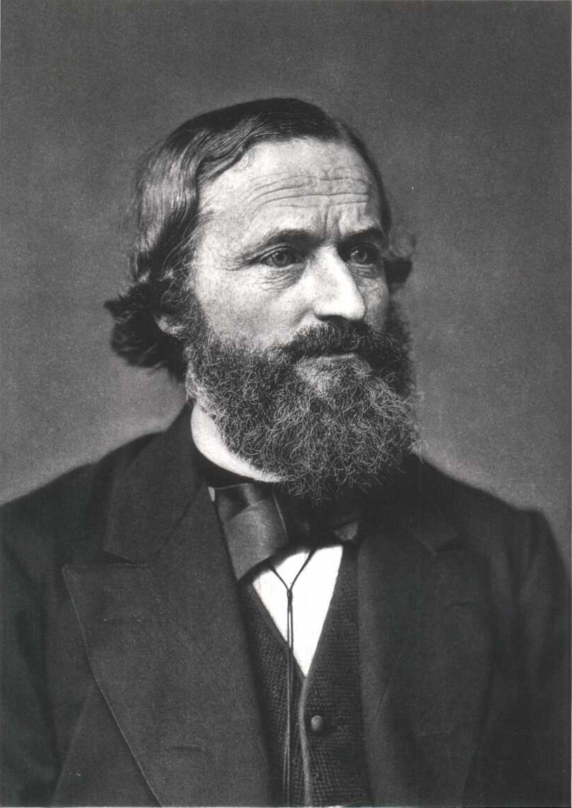
Analyzing electric circuits depends on two basic laws that were developed by the Russian scientist Justaff Kkirchhoff in 1845. They can be stated as follows:
Kirchhoff’s first Law, It is based on the principle of conservation of charge.
It states that: The sum of current that entering the junction equal the sum of current that leaves the junction.
Or The sum of all currents at a junction point in a circuit is zero, with the current entering the junction considered positive, and those leaving the junction are considered negative.
Kirchhoff’s Second Law, It is based on the principle of conservation of charge.
It states that: Around any closed path, the sum of all voltage drops on all branches within the loop is equal to the sum of the emf’s of the batteries within the loop.
Or Around any closed loop or path in a circuit, the algebraic sum of all the voltage drops must equal zero.
Try Electricity Expermints Lab for Free
PraxiLabs provides the electricity experiments lab for students, teachers, and researchers. Create your free account and enjoy conducting the many physics electricity experiments online.
You can access the virtual lab using the internet anywhere and anytime you want.