


2.5M+
Active Users Worldwide

80%
Improved Learning Retention

60%
Reduction in Laboratory Costs
Study the characteristics of the electric field by mapping the equipotential lines and constructing electric field lines of various charge configurations in an electric field mapping simulation.
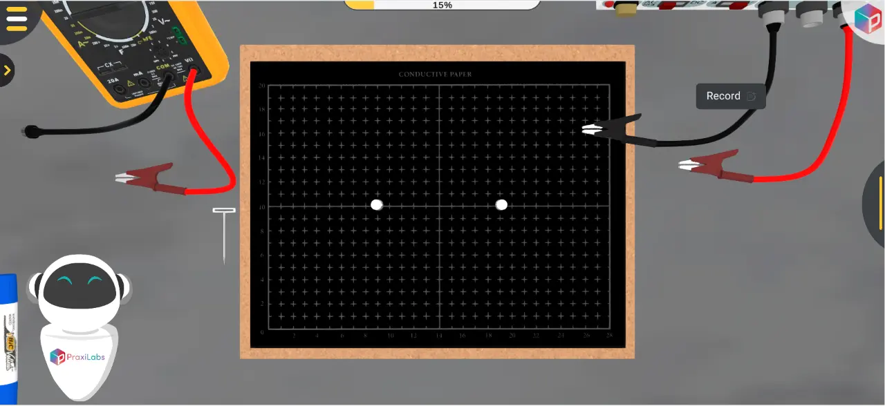
In this experiment, we will use Field Mapper Kit, Voltmeter, and DC power supply. This field mapper kit contains a lot of carbon-impregnated paper and pen, in which we can draw the equipotential lines for different patterns. If the equipotential lines are drawn, the electric field lines can be constructed as part of the mapping equipotential lines experiment.
By the end of electric field mapping simulation, the student should be able to:
These rules are written more formally as:
The concept of field lines is very useful in visualizing electric (and magnetic) fields around charges or charged objects. An electric field line, called a line of force, is an imaginary line drawn such that its direction at any point is the direction of the electric field at that point. The line starts at a positive charge and terminates on a negative charge.
By definition all the points on an equipotential line have the same potential. This implies that no work is required to move a charge from one point to another point on the same line and hence equipotential lines are perpendicular to the electric field lines everywhere.
So you will draw the equipotential lines first (using voltmeter) and then draw a number of electric field lines going from the positive charge to the negative charge and crossing the equipotential lines at right angles while mapping equipotential lines in the electric field mapping simulation.
The following are the important properties of electric field maps:
1. The number of lines crossing an area at right angles is proportional to the strength of the field. In other words where the lines are crowded, the field is strong and where the lines are sparse, the field is weak.
2. The electric field vector is tangent to the electric field line at each point.
3. The number of electric field lines leaving a positive charge or approaching a negative charge is proportional to the magnitude of the charge.
In order to draw the electric field lines, we mount the conductive paper on the corkboard using one of the metal pushpins in each corner.
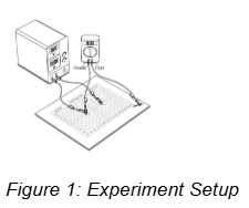
Then, connect the electrodes to the power supply using the supplied connecting wires as shown in Figure 1, which can also be demonstrated using an electric field simulation online or a 3d electric field simulation.
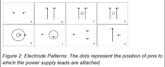
After that, we draw the electric field for different patterns using the conductive pen and conductive paper. Some suggested patterns are shown in Figure 2 to illustrate equipotential and electric field mapping.



I love the idea of virtual labs. It's gonna be something that takes our R&D and work in labs to another level. And I look forward to seeing what PraxiLabs can do with it.
Michelle Anderson, Head of Innovation
IE University - Spain
Although there are now several vendors offering virtual reality software for physics labs, there is only one that offers a realistic, I feel like I’m in a real lab solution: PraxiLabs.
Dr. William H. Miner, Jr., Professor of Physics
Palm Beach State College, Boca Raton, FL
PraxiLabs offered my students a chance to actively engage with the material. Instead of watching videos on a topic, they could virtually complete labs and realize the practical applications of class topics. This is a quality alternative to in-person labs.
Crys Wright, Teaching Assistant
Texas A&M University, USA
With the onset of the COVID-19 pandemic, we found ourselves in a situation that forced us to act quickly to find the best solution available to provide our students with a quality molecular genetics laboratory experience.
Korri Thorlacius, B.Sc., Biology Lab. Instructor
Biology Department - Kwantlen Polytechnic University